|
SERIAL RF LINK |
|
|
SERIAL RF LINK |
|
10 May 2005: Software updated
10 Feb. 2005: Schematic updated
25 January 2005: links reference corrected
24 January 2005: page created
Here is my attempt to build a serial RF link between a PC and a Handy Board that could be used by anyone interested, so that they could save the time i would have liked to save ... .
My initial goal was to release it when it would work 100% but unfortunately I still have a little problem.
I hope someone wil be able to help me to solve this problem.
Last improvment - 10 MAI 2005
The software has been improoved. It's version Le programme a été testé et amélioré. Il s'agit de la version V2.0.
On the board linked to the PC, the soft works with both tasks RF receive and RF emission activated.
On the board for the HandyBoard, the soft works only with the RF DIS-activated because of lots of falses detections. All thye problem is now to solve theses falses detections.
Here are all information needed:
Schematic
PC-board
HandyBoard-board
PCB for PC-board
warning: i made a mistake: components should be soldered on the ground side ... !PCB for HB-board
warning: i made a mistake: components should be soldered on the ground side ... !
Programs - Version V2.0version 2.0 "XTR activated" : source".asm" source ".HEX"
version 1.8: "wire testing" version : source".asm" source ".HEX"
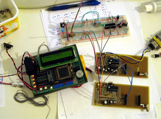
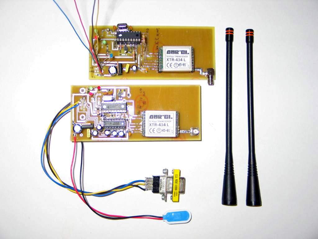
Pictures

Wire testing board RF testing boards
(wire replace XTR-434)
The Serial link uses 2 Aurel XTR - 434 Mhz transmiters. They are supposed to be nearly identical to BIM2 from Radiometrix. It needs 2 boards: the PC board and the Handy Board one. All XTR-434 are interfaced with a microcontroler 16F628 - 20 Mhz from Microchip.
The PC board have also a MAX 232 to deliver Serial level voltage.
The Handy Board one gives only TTL input and output.All is plug and play: just send a "message" of 23 bytes maximum, starting by message length and then it is received at the other end. The included microcontroler does all the manchester encoding/decoding with specific errors messages in case of error.
What is wrong:
On the initial boards, I had lots of false Radio Frequency Carrier detection. It seems that the two pins piloting the XTR-434 mode (RF receive of emit) need to be decoupled with a 100 nF capacitor. After that the false detection were greatly reduced.
The PC Board seems OK but i still have false detections with the board for the Handyboard. It seems that the RX wire connected to the handyboard causes lots of false detections that often makes the rf board stop working and need to be reseted.
I tried to connect a capacitor or a 10Kohm resistor but this didn't solve the problem.
So I hope that someone could use all the work I did to build himself an RF link and find what's wrong.
This should be easy as all the needed information is provided including the software source with lots of comments (my purpose was to help anyone that would want to buil himself such a thing), boards schematics, etc ... !
Hope this helps.
Jean-Philippe

