Here are informations for building a Hbridge that can be used with the Handy Board for connecting more powerful motors.
This H-Bridge has been described by Lyle Hazelwood, jeff Keyser and Chuck Mac Manis.
I added 1 little improvments to the circuit : an optionnal opto detector for detecting a blowed fuse
Initial Schematic from Lyle Hazelwood
New Schematic
PCB Board
3.3 cm x 9.6 cm (1 inch = 2.54 cm)
Components
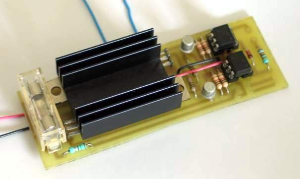
Picture
Commonents list:
R1,R2,R6,R5: 1K ohm
R3,R4: 180 ohm
R7,R8 : 330 ohm (see text for adjusting)
T1, T2: 2N2907
T3,T4: TIP 120
T5,T6: TIP 125D2,D3: diodes 1N4148
Optionnal Parts (blowed fuse detector)
R9 : 1.5 K ohm (optionnal)
IR Led: IR led from a hacked mouse or other
D1: photo resistor from a hacked mouse or other

The command is simple: connect pads 5 and 6 to the HandyBoard motor connector and that's all.
The HandyBoard drives both pads at the positive supply of the battery. When one of the motor is supposed to turn, the handyboard drives the appropriate pin at 0V. The difference between two pads makes the motor turn.
The Hbridge Board, uses this. According to the sens of the voltage difference between pads 5 and 6, the h bridge drives the motor to the appropriate sense.
R7 and R8 are 330 Ohm and supposes that the voltage between Pad 5 and 6 is about 9.6 V.
If the voltage is different, R7 and R8 must be changed according to this formula.
R (Ohm) = 0.5 * (voltage(V) - 2* 1.2)/0.01
where voltage is the maximum positive power available at pad 5 and 6 (battery power).
The purpose is to have about 10 mV across the piloting leds of the opto driver.
The opto drivers can be a 4N33 or 4N35 or others.
The Transistors are TIP 120 and TIP 125 but could be changed for more recents ones. They are supposed to drive 5 mA continous with appropriate HeatSink. They must be soldered TOP DOWN in order to be able to connect a heatsink.
WARNING: The heatsink (if in one piece) must be isolated ! T3,T4: TIP120 together and T5,T6: TIP125 together.
The opto detectors used for detecting a blowed fuse are optionnal (R9, IR
Led and D1).
- R9 is chosen in order to have about 10mV across IR Led (1.5K for a 14.4 V
battery)
- The IR Led and D1 are ar IR Led and IR resistor that cames from a hacked
computer mouse.
The IR Led and IR Resistor should be protected from the ambiant light. When the fuse is OK, the IR Led is illuminating the IR Resistor and the HandyBoard can detect it throught any analog input port. If the fuse is blowed, the IR Led isn't working and the IR Resistor increases it's resistance and this can be detected by the HandyBoard.
![]()